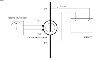
Wrong connection of the current transformers can cause false operation of the protection relays. Hence, it is vital to ensure that the current transformers are connected with the correct polarity.The figure shows a setup to test the polarity of a current transformers.A DC source is connected with the positive terminal to P1 and the negative terminal to P2. An analog voltmeter is connected to the secondary terminal of the CT. The positive terminal of the meter is connected to terminal S1 of the CT while the negative is connected to terminal S2.A contact is momentarily made through the switch. The contact is made for a second and broken. This is important as continuous contact can short-circuit the battery. The momentary make-break contact causes a deflection in the analog multimeter in the positive direction, if the polarity is correct.If the deflection is negative, it indicates that the polarity of the current transformer is reversed. The terminals S1 and S2 need to be reversed and the test can be carried out.
Saturday, May 28, 2016
Polarity test of CT
The Polarity of current transformers is extremely important. Just like a battery, a current transformer too has a polarity. The polarity determines the direction of the secondary current in relation to the primary current.
Wrong connection of the current transformers can cause false operation of the protection relays. Hence, it is vital to ensure that the current transformers are connected with the correct polarity.The figure shows a setup to test the polarity of a current transformers.A DC source is connected with the positive terminal to P1 and the negative terminal to P2. An analog voltmeter is connected to the secondary terminal of the CT. The positive terminal of the meter is connected to terminal S1 of the CT while the negative is connected to terminal S2.A contact is momentarily made through the switch. The contact is made for a second and broken. This is important as continuous contact can short-circuit the battery. The momentary make-break contact causes a deflection in the analog multimeter in the positive direction, if the polarity is correct.If the deflection is negative, it indicates that the polarity of the current transformer is reversed. The terminals S1 and S2 need to be reversed and the test can be carried out.

Wrong connection of the current transformers can cause false operation of the protection relays. Hence, it is vital to ensure that the current transformers are connected with the correct polarity.The figure shows a setup to test the polarity of a current transformers.A DC source is connected with the positive terminal to P1 and the negative terminal to P2. An analog voltmeter is connected to the secondary terminal of the CT. The positive terminal of the meter is connected to terminal S1 of the CT while the negative is connected to terminal S2.A contact is momentarily made through the switch. The contact is made for a second and broken. This is important as continuous contact can short-circuit the battery. The momentary make-break contact causes a deflection in the analog multimeter in the positive direction, if the polarity is correct.If the deflection is negative, it indicates that the polarity of the current transformer is reversed. The terminals S1 and S2 need to be reversed and the test can be carried out.
USE of CT
Current transformers are used extensively for measuring current and monitoring the operation of the power grid. Along with voltage leads, revenue-grade CTs drive the electrical utility's watt-hour meter on virtually every building with three-phase service and single-phase services greater than 200 amperes.
High-voltage current transformers are mounted on porcelain or polymer insulators to isolate them from ground. Some CT configurations slip around the bushing of a high-voltage transformer or circuit breaker, which automatically centers the conductor inside the CT window.
Current transformers can be mounted on the low voltage or high voltage leads of a power transformer; sometimes a section of a bus-bar can be removed to replace a current transformer.
The burden (load) impedance should not exceed the specified maximum value to avoid the secondary voltage exceeding the limits for the current transformer. Also, the primary current rating of a current transformer should not be exceeded or the core may enter its non linear region and ultimately saturate. This would occur near the end of the first half of each half (positive and negative) of the AC sine wave in the primary and would compromise the accuracy.
Function of CT
Function
The alternating current in the primary produces an alternating magnetic field in the core, which then induces an alternating current in the secondary. The primary circuit is largely unaffected by the insertion of the CT. Accurate current transformers need close coupling between the primary and secondary to ensure that the secondary current is proportional to the primary current over a wide current range. The current in the secondary is the current in the primary (assuming a single turn primary) divided by the number of turns of the secondary. In the illustration on the right, 'I' is the current in the primary, 'B' is the magnetic field, 'N' is the number of turns on the secondary, and 'A' is an AC ammeter.
The most basic current transformer comprises the secondary wound around the primary conductor, but typically current transformers consist of a silicon steel ring core wound with many turns of copper wire as shown in the right illustration. The conductor carrying the primary current is then passed through the ring; the CT's primary therefore consists of a single 'turn'. The primary 'winding' may be a permanent part of the current transformer, with a heavy copper bar to carry current through the core. Window-type current transformers (aka zero sequence current transformers, or ZSCT) are also common, which can have circuit cables run through the middle of an opening in the core to provide a single-turn primary winding. To assist accuracy, the primary conductor should be central in aperture.
Current Transformer
When a current is too high to measure directly or the voltage of the circuit is too high, a current transformer can be used to provide an isolated lower current in its secondary which is proportional to the current in the primary circuit. The induced secondary current is then suitable for measuring instruments or processing in electronic equipment. Current transformers also have little effect on the primary circuit. Often, in electronic equipment, the isolation between the primary and secondary circuit is the important characteristic.
Current transformers are used in electronic equipment and are widely used for metering andprotective relays in the electrical power industry
Saturday, May 21, 2016
Distribution transfomer
Construction
Distribution transformers are made using a core made from laminations of sheet steelstacked and either glued together with resin or banded together with steel straps. Where large numbers of transformers are made to standard designs, a wound C-shaped core is economic to manufacture. A steel strip is wrapped around a former, pressed into shape and then cut into two C-shaped halves, which are re-assembled on the copper windings.
The primary coils are wound from enamel coated copper or aluminum wire and the high current, low voltage secondaries are wound using a thick ribbon of aluminum or copper. The windings are insulated with resin-impregnated paper. The entire assembly is baked to cure the resin and then submerged in a powder coated steel tank which is then filled withtransformer oil (or other insulating liquid), which is inert and non-conductive. The transformer oil cools and insulates the windings, and protects the transformer winding from moisture, which will float on the surface of the oil. The tank is temporarily depressurized to remove any remaining moisture that would cause arcing and is sealed against the weather with a gasket at the top.
Formerly, distribution transformers for indoor use would be filled with a polychlorinated biphenyl (PCB) liquid. Because these liquids persist in the environment and have adverse effects on animals, they have been banned. Other fire-resistant liquids such as silicones are used where a liquid-filled transformer must be used indoors. Certain vegetable oils have been applied as transformer oil; these have the advantage of a high fire point and are completely biodegradable in the environment.
Pole-mounted transformers often include accessories such as surge arresters or protective fuse links. A self-protected transformer includes an internal fuse and surge arrester; other transformers have these components mounted separately outside the tank. Pole-mounted transformers may have lugs allowing direct mounting to a pole, or may be mounted on crossarms bolted to the pole. Aerial transformers, larger than around 75 kVA, may be mounted on a platform supported by one or more poles. A three-phase service may use three identical transformers, one per phase.
Transformers designed for below-grade installation can be designed for periodic submersion in water. [
Distribution transformers may include an off-load tap changer to allow slight adjustment of the ratio between primary and secondary voltage, to bring the customer voltage within the desired range on long or heavily loaded lines.
Pad-mounted transformers have secure locked and bolted grounded metal enclosures to discourage unauthorized access to live internal parts. The enclosure may also include fuses, isolating switches, load-break bushings, and other accessories as described in technical standards. Pad-mounted transformers for distribution systems typically range from around 100 to 2000 kVA, although some larger units are also used.
Distribution transformer
A distribution transformer or service transformer is a transformer that provides the final voltage transformation in the electric power distribution system, stepping down the voltage used in the distribution lines to the level used by the customer. The invention of a practical efficient transformer made AC power distribution feasible; a system using distribution transformers was demonstrated as early as 1882.
Classification
Distribution transformers are classified into different categories based on certain factors such as:
- Mounting location – pole, pad, underground vault
- Type of insulation – liquid-immersed or dry-type
- Number of Phases – single-phase or three-phase
- Voltage class
- Basic impulse insulation level (BIL).
Use
Distribution transformers are also found in the power collector networks of wind farms, where they step up power from each wind turbine to connect to a substation that may be several miles (kilometres) distant. The number of customers fed by a single distribution transformer varies depending on the number of customers in an area. Several homes may be fed off a single transformer in urban areas; rural distribution may require one transformer per customer. A large commercial or industrial complex will have multiple distribution transformers. Padmount transformers are used in urban areas and neighborhoods where the primary distribution lines run underground. Many large buildings have electric service provided at primary distribution voltage. These buildings have customer-owned transformers in the basement for step-down purposes. In a secondary network system as used in urban areas, many distribution transformers may be connected in parallel, each equipped with its own network protector circuit breaker to isolate it from the secondary network in case of a fault.
Distribution transformers are normally located at a service drop, where wires run from a utility pole or underground power lines to a customer's premises. They are often used for the power supply of facilities outside settlements, such as isolated houses, farmyards or pumping stations at voltages below 30 kV. Another application is the power supply of the overhead wire of railways electrified with AC. In this case single phase distribution transformers are used.
Subscribe to:
Posts (Atom)